Power feels simple until voltage has to travel hundreds of miles. Then losses rise, outages happen, and equipment fails. A transformer solves this by changing voltage safely and efficiently.
Transformers let the grid move power at high voltage and low current for long distance, then step it down in layers so people and equipment can use it safely at the load.

If I keep the explanation grounded in how the grid is built, engineers and buyers usually understand faster, and they also ask better questions during specification and bidding.
What is a transformer used for?
If voltage stays low, current stays high. Then conductors heat up, losses increase, and the system needs thicker cables and more equipment. That costs money and still gives weak performance.
A transformer is used to trade voltage for current in AC systems, so transmission runs at high voltage with low loss, and distribution runs at safer voltage near customers.

In daily project work, I describe transformers as the “gearbox” of the grid. We do not move power one voltage level from generation to the customer. We move it through steps. Each step is linked to distance, safety, equipment insulation, and fault behavior1.
Why high voltage is used on long lines
Power on a line is roughly voltage times current. If I keep power the same and I increase voltage, current drops. Lower current reduces heating loss in the line. That heating loss is strongly tied to current squared, so a small current drop can reduce loss a lot. This is why long-distance transmission uses very high voltage.
Where the transformer sits in the grid
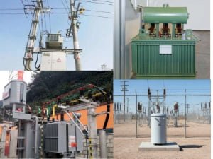
- Step-up transformers near generation or major substation2s raise voltage for long lines.
- Step-down transformers in fenced substations reduce voltage for city and industrial networks.
- Distribution transformers near customers reduce voltage again to utilization levels.
This chain is the reason transformers are not optional in modern grids. They are the grid.
What is the basic definition of a transformer?
Many teams get stuck because they mix the physical device with the system behavior. I try to keep the definition short, then I add the engineering logic.
A transformer is a static AC device that transfers energy by magnetic coupling between windings, stepping voltage up or down in proportion to turns ratio while keeping the same frequency.

The basic relationship I use early is the turns ratio3. If losses are ignored, voltage scales with turns, and current scales in the opposite direction.
Ideal relationships I use as a first check
| Item | Ideal relationship | What it means in simple words |
|---|---|---|
| Voltage | Vp / Vs = Np / Ns | More turns gives more voltage |
| Current | Ip / Is = Ns / Np | Higher voltage side carries lower current |
| Power | Vp×Ip ≈ Vs×Is | Power is close, minus losses |
So if the primary has 50 turns and the secondary has 100 turns, the secondary voltage is about double. In real units, there are core losses and copper losses4, plus leakage reactance that creates voltage drop under load. Still, the turns ratio is the anchor. I use it to sanity-check nameplates, drawings, and tender specs before we talk about details like impedance, temperature rise5, and insulation class.
How do transformers work for dummies?
People memorize “electromagnetic induction6,” but they cannot picture the steps. Then they get confused about DC, overload, and fault forces.
AC in the primary makes a changing magnetic flux in the core, and that changing flux induces a voltage in the secondary. The load then draws current, and the primary supplies matching power.

I explain it in a fixed sequence, because that avoids myths.
The sequence that matches what I see in tests
- I apply AC voltage7 to the primary winding.
- Magnetizing current creates a changing flux in the core.
- That flux links the secondary winding.
- The secondary sees induced voltage.
- When a load is connected, secondary current flows.
- Primary current increases to supply the load power.
The important point is that the energy transfer is through the magnetic field, not through a direct conductor connection between primary and secondary. That is why insulation, clearances, and core build quality matter so much. In a factory, I can measure ratio, losses, and impedance. On a site, I can see the results through voltage regulation, heating, and fault performance.
Where does voltage step down in the United States?
People often think “the grid is one voltage.” In the US, the system is layered, and the steps are built around substations and local feeders. If you miss one layer, you will misunderstand the equipment.
In the US, common transmission levels include 345 kV and 138 kV, then it steps down to subtransmission like 69 kV or 34.5 kV, then distribution is often around 12 kV or 4 kV before final customer voltages.

This is the part that I see buyers and junior engineers benefit from the most, because it connects voltage numbers to physical locations.
A practical US voltage ladder I often reference
| Grid layer | Typical voltage examples | Where I usually see it |
|---|---|---|
| Transmission | 345 kV, 138 kV | Major substations, long lines |
| Subtransmission | 69 kV, 34.5 kV | Regional substations, feeder heads |
| Distribution | 12 kV, 4 kV | Local feeders, distribution substations |
| Utilization | 240/120, 480/277, 208/120 | Customer service entrance |
Most of these voltage changes happen inside fenced substations. When the site is a dense downtown area, you might not see a yard. You might see underground vaults instead. Still, the function is the same: switching, protection, and voltage transformation.
I also highlight that “distribution” can mean different things depending on the utility and the city. Some areas have 13.2 kV, 13.8 kV, 12.47 kV, 4.16 kV, and more. The exact number matters for insulation level, clearances, and protection settings, but the system idea is the same.
How is distribution handled near the customer?
If voltage stays high all the way to a house, it is dangerous and impractical. If voltage drops too early, losses rise. So the last step happens near the load.
Utilities use pole-mounted transformers8 for overhead lines or pad-mounted transformers for underground networks, installed close to customers to reduce low-voltage drop and keep the system stable.

When I walk a site with a client, this is the first transformer they can touch and point at. It is also the one that causes the most public attention when it fails, because it sits in neighborhoods.
Pole-mounted vs pad-mounted in simple project terms
| Type | Typical application | What I watch during design and supply |
|---|---|---|
| Pole-mounted | Overhead distribution | Lightning exposure, surge arresters, storm risk |
| Pad-mounted | Underground distribution | Sealing, corrosion, tamper resistance, cabinet layout |
In North America, a lot of these are small units, and failures do happen. I see storm periods as the big driver. Wind and tree contact cause faults. Lightning causes surges. Reclosing cycles stress equipment. This is why utilities invest in arresters, grounding, and protection coordination.
In contrast, substation transformer failures can be rare, but they can be severe. When a big unit fails, the energy and the impact are much larger. Operators plan for this with spares, mobile units, network redundancy, and careful protection settings. I tell buyers that “rare” does not mean “ignore.” It means you manage risk through design margin and operational plans.
What is residential voltage9 in North America, and why does it look strange?
Many engineers from outside North America expect a single-phase two-wire home supply. Then they see split-phase and get confused. That confusion can lead to wrong equipment selection.
Most US and Canadian homes use 240 V split-phase service10: two hot conductors and one neutral. Each hot-to-neutral is 120 V, and hot-to-hot is 240 V.

I keep the explanation practical. Split-phase gives two common utilization voltages without bringing in full three-phase service. It also balances loads across the two legs. Many household loads run on 120 V. Larger loads like some HVAC, ranges, dryers, and EV chargers often use 240 V. The service transformer secondary is typically center-tapped, and the center tap is the neutral.
What I tell buyers who ship equipment into North America
- If you design only for 230 V single-phase, you may miss the 120 V leg loads.
- If you assume three-phase is present in every building, you will over-design.
- For commercial and light industrial, three-phase is common, and LV may be 480/277 or 208/120 depending on the customer and the local practice.
That last point matters for transformer configuration, switchgear, and metering. I have seen projects lose weeks because the team assumed 480 V was always available. It was not. Then they had to rework motor starters and distribution panels.
What winding connections11 are common, and what changes slightly electrically?
If the connection choice is wrong, grounding behavior and fault response will surprise you. That can cause nuisance trips or worse.
A common utility practice is a delta primary and a wye secondary for distribution and many commercial services, because it supports grounding on the LV side and manages certain unbalanced and harmonic behaviors.

Here are actually some slight electrical changes when we talk about winding connections. When I say “slight,” I mean the transformer still does voltage conversion, but the system behavior around grounding, phase shift, and fault current can change in important ways.
Here you can see the primary winding in delta. In this setup, the delta can provide a closed path for certain components, and the wye secondary gives a neutral point. That neutral is valuable for 4-wire systems and for protection. Many commercial and light industrial customers want a grounded neutral on the LV side.
Typical LV options I see for commercial and light industrial
| LV service | Where I often see it | What it implies |
|---|---|---|
| 480/277 V | Larger commercial, HVAC heavy | 277 V line-to-neutral lighting loads |
| 208/120 V | Offices, mixed small loads | Many 120 V loads, smaller motors |
This is also where customization matters. Country standards set the baseline, but project conditions decide the final build. I always ask the customer about grounding method, load mix, harmonics, and future expansion. Then I lock the vector group, impedance, losses, temperature rise, and accessory set based on that.
No matter which national standard you follow, and no matter the custom need, you can reach out to me. At YEEG, I can provide transformer customization that matches your requirement, and I support you with a practical and stable delivery process.
Conclusion
Transformers make the grid workable by stepping voltage through transmission, subtransmission, distribution, and customer levels, with connection choices that shape real fault and grounding behavior.
-
Understanding fault behavior is crucial for designing safe electrical systems. ↩
-
Understand how substations manage voltage levels in the power distribution network. ↩
-
Understanding turns ratio is crucial for calculating voltage and current in transformers. ↩
-
Learn about copper losses to improve the efficiency of your transformer systems. ↩
-
Find out how to manage temperature rise to ensure transformer longevity. ↩
-
Learn the principles of electromagnetic induction that make transformers work. ↩
-
Explore the impact of AC voltage on the functioning of transformers. ↩
-
Discover the applications and benefits of pole-mounted transformers in distribution. ↩
-
Get to know the residential voltage standards to ensure proper equipment selection. ↩
-
Learn about split-phase service to better understand residential electrical systems. ↩
-
Understand how winding connections impact transformer performance and safety. ↩