Are you wondering what those gray boxes on utility poles are? They seem complex and mysterious, but their job is simple. Here’s the straightforward explanation you’ve been looking for.
A transformer is a static electrical device that changes the voltage of an Alternating Current (AC). It steps voltage up for efficient long-distance transmission and steps it down for safe use in homes and businesses, all without any moving parts. It’s the backbone of our power grid.

Now that you know the basic function, you probably want to understand how this simple box makes our entire electrical world possible. Let’s look at how they work and where you find them in your daily life.
What is a transformer used for?
You see power lines running for miles, but how does the electricity get to you without losing all its energy? It’s a big problem. The solution is a device you see everywhere.
Transformers are mainly used to change voltage levels in a power grid. We use "step-up" transformers to increase voltage for efficient long-distance transmission and "step-down" transformers to lower it to safe levels for homes and businesses, minimizing energy loss1.

When I design a transformer solution for a client, the first thing we discuss is its purpose. Will it be stepping up power from a new solar farm, or stepping it down for a new housing development? The application defines the entire design.
The core reason we need them comes down to a simple physics problem. When electricity travels through a wire, some energy is lost as heat. This loss is calculated by the formula Power Loss = I²R2, where ‘I’ is the current and ‘R’ is the resistance of the wire. Notice the current is squared. This means if you can cut the current in half, you reduce the energy loss by 75%.
So, how do we reduce the current? This is where the transformer comes in. The total power on a line is Voltage multiplied by Current3 (P = V x I). To send the same amount of power, if I use a transformer to increase the voltage by 100 times, the current drops by 100 times. This drastically cuts down the heat loss in the transmission lines.
This is why we have:
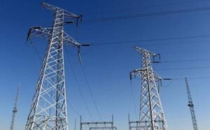
- Transmission Lines4: The giant metal towers carrying power for hundreds of miles operate at very high voltages, like 325,000 volts or more. The current is low, so energy loss is minimal.
- Distribution Lines5: When the power reaches a city, substation transformers step the voltage down to a medium level, like 12,000 volts, for distribution around neighborhoods.
- End-Use: A final transformer, maybe on a pole or a green pad in your yard, steps it down again to the 120/240 volts that your home can safely use.
Every step is about balancing efficiency with safety, and the transformer makes it all possible.
What is the basic definition of a transformer?
Engineers use a lot of jargon, which can be confusing. You need a clear, basic definition of a transformer without the complex terms. Here is what it really is.
A transformer is a static electrical device that transfers energy between two or more circuits through electromagnetic induction6. It is designed to change the voltage level of an AC circuit while keeping the frequency the same. It does not have any moving parts.

When I specify a transformer, I’m not just ordering a box. I’m defining a system of core components that must work together perfectly. At its heart, a transformer only has a few main parts, but the quality of these parts determines its entire life and performance.
Core Components of a Transformer
| Component | Role | My Preferred Materials |
|---|---|---|
| Iron Core | Guides the magnetic field efficiently from one coil to the other. Minimizes energy loss. | High-grade Cold-Rolled Grain-Oriented (CRGO) silicon steel. We stack it in thin, insulated layers (laminations) to reduce heat losses. |
| Windings | The coils of wire where the electrical energy is converted to magnetic energy and back. There is a primary (input) and secondary (output) winding. | Electrolytic copper is my first choice for its excellent conductivity. We use aluminum when cost or weight is a primary project constraint. |
| Insulation | Prevents short circuits between windings, and between the windings and the core. This is the most critical part for transformer longevity. | We use a system of transformer-grade insulation paper, pressboard, and insulating fluid (like mineral oil or an alternative). |
| Tank & Cooling System | Contains the core and windings, protects them from the environment, and dissipates heat generated during operation. | For oil-immersed transformers, this is a sealed steel tank, often with cooling fins or radiators. For dry-type transformers, it’s a ventilated enclosure. |
I treat every one of these parts as critical. For example, the core isn’t just a lump of iron; it’s precisely cut and stacked to ensure the magnetic field is channeled perfectly. The windings aren’t just wrapped wire; the tension and layering are controlled to withstand huge magnetic forces during a fault. It’s this engineering focus on the fundamentals that separates a reliable transformer from one that will fail prematurely.
How do transformers work for dummies?
The physics behind transformers sounds complicated. All the talk about magnetic fields and induction can be intimidating. But the core idea is actually very simple and works in a few logical steps.
Imagine two separate coils of wire wrapped around the same iron loop. AC current in the first coil creates a changing magnetic field in the iron. This changing field then creates a new AC current in the second coil, but at a different voltage.

Let’s break that down. The whole process relies on one basic principle from physics called Faraday’s Law of Induction7, which simply says that a changing magnetic field will create a voltage in a nearby wire.
Here is the step-by-step process:
- AC Power In: We connect an AC power source to the first coil, called the primary winding. Because the current is AC, it’s constantly changing direction and strength.
- Creating a Magnetic Field: This changing current creates a magnetic field in the iron core that is also constantly changing and flipping direction. The iron core is special because it’s very good at containing and guiding this magnetic field.
- Transferring the Field: The iron core channels this moving magnetic field over to the second coil, called the secondary winding. Almost no magnetic energy is lost along the way.
- Inducing a New Voltage: Because the magnetic field passing through the secondary winding is always changing, it "induces" a new AC voltage in that coil. A new current can now flow from this secondary coil to power a load.
The magic is in the number of turns in each coil. If the secondary coil has more turns of wire than the primary, the voltage will be higher (a step-up transformer). If it has fewer turns, the voltage will be lower (a step-down transformer). The ratio is direct. If the primary has 100 turns and the secondary has 200 turns, the voltage will double. This simple, reliable principle is what makes our entire power grid function.
What happens when a transformer blows?
You hear a loud bang, the lights go out, and you see smoke. A transformer failure is dramatic and dangerous. It’s more than just a fuse blowing; it’s a violent event.
When a transformer "blows," it means a severe internal electrical fault has occurred. This fault creates an arc8 that instantly vaporizes the insulating oil, causing a massive pressure buildup that ruptures the tank. This results in an explosion, fire, and a power outage.

In my line of work, failure analysis is key to improving future designs. A transformer doesn’t just spontaneously explode. It’s a chain reaction that almost always starts with the failure of one thing: the insulation.
Here’s the typical sequence of events for a catastrophic failure:
- Insulation Breakdown9: The process begins when the insulation inside the transformer—either the oil or the paper around the windings—fails. This can be caused by years of heat stress, a lightning strike that punctures it, or moisture contamination that weakens it.
- The Arc: Once the insulation is breached, a high-current electrical arc, like a bolt of lightning, flashes between the windings or from a winding to the grounded tank.
- Pressure Buildup: This arc is incredibly hot (thousands of degrees). It instantly vaporizes the surrounding mineral oil, changing it from a liquid to a massive volume of gas in a microsecond. The transformer tank is sealed, so this gas has nowhere to go.
- The Explosion: The internal pressure skyrockets and the steel tank ruptures violently. This is the loud "bang" people hear. The pressure wave can be strong enough to throw parts hundreds of feet.
- The Fire: When the tank ruptures, the hot, flammable mineral oil is often ejected and ignites on contact with the air, creating a serious fire that can be difficult to extinguish.
At the same time, protective devices like fuses or circuit breakers on the power line will detect the massive current surge from the fault and trip, cutting off power to the transformer and the surrounding area. This is why a single transformer failure can cause a neighborhood-wide outage. Good design, quality manufacturing, and proper protection are all critical to prevent this from happening.
Who is the most popular transformer?
When someone asks me what the most popular transformer is, I have to smile. Am I talking about Optimus Prime or power grids? In my world, the answer is clear and simple.
In the power industry, the most popular and common type is the oil-immersed distribution transformer10. These are the workhorses of the grid, seen on utility poles or as green boxes in neighborhoods, doing the final job of stepping down voltage for homes.

While large substation transformers are the heart of the grid, distribution transformers are the capillaries that deliver power to every single user. There are millions of them in service. When you flip a light switch, you are using power that has just passed through one of these.
They come in two main forms you’ve definitely seen:
- Pole-Mounted Transformers: These are the gray, cylindrical cans you see hanging on utility poles, typically serving a small group of houses. I’ve helped design thousands of these, and each utility has its own specific requirements for bushings, connectors, and mounting brackets.
- Pad-Mounted Transformers: These are the locked, green metal cabinets that sit on a concrete slab on the ground, common in areas with underground power lines like newer housing developments or commercial areas. They serve a larger number of customers than a single pole-mounted unit.
Their job is to take the medium-voltage power from the local lines (e.g., 7,200 or 12,470 volts) and step it down to the safe, usable 120/240 volts your wall outlets provide. As an OEM manufacturer, these units are a huge part of what we do. We customize them for clients all over the world, ensuring they meet local standards and can handle the specific environmental conditions, whether it’s the heat of the Middle East or the cold of Canada. They may not be famous robots, but they are the true heroes of the electrical world.
Where are transformers used in real life?
Transformers seem like industrial equipment, hidden away from public view. You might not realize they are working all around you, 24/7. They are absolutely everywhere, from the power plant to your pocket.
Transformers are used in every stage of the power grid, in every industrial facility, and inside many electronic devices. You’ll find them in massive substations, on utility poles, in green boxes in your yard, and even inside your phone charger.

I’ve worked on projects that put transformers in a huge variety of environments. Thinking about their journey helps to see how essential they are.
In the Power Grid
This is their primary and most visible role. The grid is a multi-stage system built around transformers.
- At the Power Plant: Giant Generator Step-Up (GSU) transformers take the voltage produced by generators and increase it to extremely high levels (e.g., 500,000 volts) for transmission.
- In Transmission Substations: After traveling long distances, the power arrives at a substation where large transformers step the voltage down to a sub-transmission level (e.g., 69,000 volts).
- In Distribution Substations: Closer to your city, smaller substation transformers step it down again to medium voltage (e.g., 12,000 volts) to run on local power lines.
- At Your Neighborhood: A pole-mounted or pad-mounted distribution transformer performs the final step-down to the 120/240 volts used by your home.
Beyond the Grid
Their use doesn’t stop at the utility pole.
- Industrial Plants: Factories use transformers to provide specific voltages for heavy machinery like large motors, welders, and furnaces.
- Commercial Buildings: Large buildings have dry-type transformers indoors to power HVAC systems, elevators, and lighting panels.
- Renewable Energy: Wind and solar farms use transformers to step up the low voltage they generate to match the grid’s voltage for injection. This is a huge and growing market for my company.
- Consumer Electronics: That little black box on your laptop’s power cord is part of a power supply that uses a tiny transformer to convert the wall’s AC voltage to the low-voltage DC your device needs.
From generating megawatts of power to charging your phone, a transformer is almost always involved.
What are the 4 types of transformers?
Hearing about all the different transformers can be confusing. Are they categorized by size, function, or something else? Let’s simplify it by breaking them down into four common functional groups.
A simple way to classify transformers is by their function and application: step-up, step-down, distribution, and instrument transformers. The first two describe what they do to voltage, while the last two describe their specific role in the power system.

| As an engineer, I think about transformers in multiple ways, but these four categories are a great starting point for any project discussion. | Transformer Type | Primary Function | Common Location |
|---|---|---|---|
| 1. Step-Up Transformer | Increases voltage (and decreases current). | At power generation plants, before electricity enters long-distance transmission lines. | |
| 2. Step-Down Transformer | Decreases voltage (and increases current). | At substations and at the final delivery point to customers. | |
| 3. Distribution Transformer | A specific class of step-down transformer used for the final voltage reduction before use in homes and businesses. | On utility poles, on concrete pads, or in building vaults. | |
| 4. Instrument Transformer | Not used to transfer power. Used for measurement and protection by safely reducing high voltages and currents to low levels for meters and relays. | In substations and switchgear, connected to monitoring equipment. |
The first three types are all about power transfer. The fourth, instrument transformers, is different. A project engineer like Michael will rely on these to get accurate data about his power system’s health. They include Current Transformers (CTs) and Potential Transformers (PTs) and are critical for safety and control.
Another very common way I classify transformers is by their cooling method:
- Oil-Immersed: The core and windings are submerged in a tank of mineral oil that provides both cooling and insulation. These are the most common type for outdoor utility applications.
- Dry-Type: These use air and solid resin insulation for cooling. They are used indoors where an oil leak would be a fire hazard, such as in hospitals, airports, and commercial high-rises.
So when a client asks for a "step-down transformer," my next question is always, "Oil-immersed or dry-type?" The application dictates everything.Are transformers AC or DC?
You may wonder if transformers work with both types of electricity, AC and DC. This is a critical question, and the answer is fundamental. Getting it wrong is both ineffective and dangerous.
Transformers work only with Alternating Current (AC). They cannot function with Direct Current (DC) and should never be connected to a DC source. Their entire operation depends on the changing nature of AC.

To understand why, we have to go back to how a transformer works: it needs a changing magnetic field to induce a voltage in the secondary coil.
- With Alternating Current (AC): AC power naturally and continuously changes direction and magnitude, creating the constantly changing magnetic field that is essential for induction. The transformer works as intended.
- With Direct Current (DC): DC power flows in only one direction at a constant level. When you connect it to the primary winding, it creates a magnetic field that is strong but static. It doesn’t change. Since the magnetic field isn’t changing, no voltage is induced in the secondary coil. The transformer produces zero output.
But it gets worse than just not working. Connecting a transformer to a DC source is extremely dangerous. The primary winding of a transformer is essentially a very long piece of wire with very low electrical resistance. With AC, the winding has a high impedance, which limits the current to a safe level. With DC, this impedance effect is gone. According to Ohm’s Law (I = V/R), if the resistance (R) is nearly zero, the current (I) will become massive. This huge current will instantly overheat the primary winding, melting the wire’s insulation and destroying the coil. It’s the equivalent of a dead short circuit, which can cause fires and damage the DC power source. This is one of the first lessons every electrical engineer learns.What is the lifespan of a transformer?
When you’re managing a project, you need to know how long your equipment will last. You’re not just buying a product; you’re investing in decades of reliable service. So what’s a realistic expectation?
A well-designed, properly manufactured power transformer should have a service life of 25 to 40 years. However, this lifespan is heavily dependent on how it’s operated, how well it’s maintained, and the quality of the materials used to build it.

The life of a transformer is really the life of its insulation system. The paper insulation wrapped around the copper windings is the most vulnerable part. Over time, heat causes this paper to become brittle and weak. Once the paper can no longer insulate the windings, a short circuit occurs, and the transformer’s life is over.
I always tell my clients that three main factors determine how long their investment will last:
- Heat and Loading: Heat is the number one enemy. Consistently running a transformer above its rated capacity (overloading) generates excessive heat, which drastically accelerates the aging of the insulation. A transformer operated in a hot desert climate will age faster than one in a cool northern region.
- Moisture: Moisture is the second enemy. If moisture gets into the insulating oil, it’s a huge problem. It lowers the oil’s ability to insulate and directly attacks the cellulose paper, breaking it down chemically. This is why a good sealing system is non-negotiable in my designs.
- Manufacturing Quality: This is where everything starts. A transformer that isn’t properly dried under vacuum at the factory will have moisture trapped in its insulation from day one. Using low-grade materials or a poor oil-filling process can doom a transformer to a short life. I stand by our manufacturing processes because I know they are designed to maximize the lifespan of the insulation system, giving our clients the 40-year reliability they expect. Regular maintenance, like testing the oil for contaminants, is also crucial to catch problems early.
What is the most common cause of transformer damage?
You need to protect your assets from failure. Understanding the primary threats to a transformer’s health is the first step in ensuring its long and reliable service life. These are the culprits I see most often.
The most common causes of transformer damage are external events like lightning strikes and internal degradation from overloading, moisture, and simple aging. These factors lead to insulation failure, which is the root cause of almost all catastrophic transformer failures.

From my experience reviewing failure reports and designing robust transformers, the damage can be broken down into two main categories: things that happen to the transformer, and things that happen inside it.
External Events
These are sudden, high-energy events that a transformer must be built to withstand.
- Lightning: A direct or nearby lightning strike sends a massive voltage surge, or transient overvoltage, through the windings. This can be thousands of times the normal operating voltage and can easily puncture the insulation, causing an immediate short circuit. Properly sized surge arresters are the main line of defense.
- Through-Faults: When a short circuit happens somewhere else down the power line (like a tree falling on the wires), a huge amount of current rushes through the transformer to feed the fault. This creates intense magnetic forces that can physically bend or damage the windings if they are not braced and wound securely.
Internal Conditions
These are slower-acting killers that degrade the transformer over time.
- Overloading: Consistently running a transformer beyond 100% of its rated power creates excessive heat. This heat is the primary accelerator of insulation aging. It’s a slow death, but it’s guaranteed.
- Insulation Degradation: This is the ultimate cause of death for most transformers. The solid paper and liquid oil insulation breaks down due to:
- Moisture: From tiny leaks in gaskets or even from being built in a humid factory without proper drying processes.
- Oxidation: The oil reacts with oxygen over time, creating sludge that blocks cooling ducts and causes overheating.
- Thermal Aging: After decades of heat cycles, the cellulose paper insulation simply becomes too brittle and weak to withstand electrical and mechanical stress.
My job as a manufacturer is to build a transformer that is robust against both external shocks and internal decay. Michael’s job as a project engineer is to specify the right protection and ensure a good maintenance plan is in place. Together, we can ensure the transformer has a long, productive life.
Conclusion
Transformers are simple, essential devices that use magnetic fields to change AC voltage. This function is vital for efficiently and safely transmitting power from plants to you, making them indispensable.
-
Discover the factors contributing to energy loss and how transformers help mitigate this issue. ↩
-
This formula is key to understanding how current and resistance affect energy loss in wires. ↩
-
Grasp the relationship between voltage, current, and power to understand transformer functionality. ↩
-
Learn about the infrastructure that carries high-voltage electricity over long distances. ↩
-
Explore how distribution lines deliver electricity from substations to neighborhoods. ↩
-
Delve into the principle that allows transformers to transfer energy between circuits. ↩
-
Learn about the fundamental principle that underpins how transformers operate. ↩
-
Understand the dangers of electrical arcs and their role in transformer failures. ↩
-
Discover the common causes of transformer failures and how to prevent them. ↩
-
Explore the most common type of transformer used in power distribution. ↩