Expanding a distribution grid is rarely a “swap in a bigger transformer” exercise. A sound capacity decision must balance current demand, forecast growth, supply reliability, and lifecycle economics—with one clear engineering objective: avoid chronic light-loading (“oversized transformer1”) or sustained overloading.
In practice, transformer sizing should be based on verified load data2 (or defensible estimates), the correct conversion from kW to kVA, and project constraints such as voltage regulation3, motor starting4, load criticality, seasonal variability5, installation environment, and N-1/contingency requirements.
Below, the methodology is organized around four practical questions that utilities, EPCs, and industrial owners typically ask during grid expansion.

How to calculate load on distribution transformer?
1) Start with what actually drives transformer loading: kVA, not just kW
A transformer is thermally and electrically stressed primarily by apparent power (kVA) and current—not by kW alone. Therefore, the first rule is to convert real power demand to kVA using power factor (PF)6 and—when applicable—adjust for harmonics and imbalance.
Core conversion
- S (kVA) = P (kW) / PF
If PF is unknown, do not assume “0.8 by default” unless that matches the load profile. Use measured PF where possible, because PF variation can materially change the transformer kVA requirement.
2) Build a defensible maximum demand (not a nameplate sum)
When expanding a distribution grid, errors often come from confusing:
- Connected load: the sum of nameplate ratings
- Maximum demand / diversified peak: the realistic peak when diversity and simultaneity are considered
- Transformer loading: peak demand converted to kVA and evaluated under constraints
A practical approach is:
- Survey site conditions: supply voltage level, feeder configuration, ambient conditions, installation constraints.
- Inventory loads by type (motors, HVAC, lighting, process loads, EV chargers, UPS/VFD, etc.).
- Apply demand / diversity / simultaneity assumptions appropriate to the user segment (residential, commercial, industrial, mixed).
- Identify the peak operating scenario (daily/weekly/seasonal) and compute maximum diversified kW.
- Convert to kVA using measured or justified PF.
3) Account for three-phase imbalance7 explicitly (especially at LV)
LV networks often develop phase imbalance7 due to single-phase loads (lighting, plug loads, small HVAC). A simple, conservative engineering method is to calculate by phase and size to the worst phase.
Phase-based method
- Sum A/B/C phase real power separately: (P_A, P_B, P_C)
- Single-phase loads are assigned to their actual phase.
- Three-phase load real power may be divided by 3 for phase-level estimation.
- Take the maximum: (P_{max} = \max(P_A, P_B, P_C))
- Estimate total three-phase peak: (P{3\phi} \approx 3 \times P{max})
- Convert to kVA: (S = P_{3\phi} / PF)
This method helps prevent under-sizing when one phase is heavily loaded.
4) Use a target loading band8 to avoid “oversize” and “overload”
A useful planning rule is to keep normal operation in a rational loading band:
- Typical normal loading: 75–90% of rated kVA (project-dependent)
- Chronic <50%: often indicates oversizing → higher no-load loss share and poorer economics
- Sustained >100%: unacceptable unless explicitly justified by emergency rating and thermal limits
This band should be validated against load growth expectations and reliability requirements. For example, a fast-growing area may intentionally accept lower initial loading to avoid early replacement—provided losses and budget are justified.
How to size a distribution transformer?
Sizing is best treated as a capacity decision under constraints, not a single arithmetic step. A robust workflow includes voltage selection, peak kVA calculation, reliability strategy, and operational checks (motor starting, seasonal peaks).
1) Confirm voltage levels and secondary system requirements
Transformer voltage selection is not only a “match the grid” step—it affects voltage regulation3 and customer-side performance.
- Primary (HV/MV) rated voltage: matches the connected feeder/bus voltage.
- Secondary (LV) rated voltage: matches utilization voltage and system design.
- Prefer LV three-phase four-wire where applicable to supply both power and lighting loads efficiently and improve distribution flexibility.
2) Calculate required kVA from diversified peak demand9
Compute diversified peak demand and convert to kVA:
- (S{peak} (kVA) = \dfrac{P{peak} (kW)}{PF})
Then apply an engineering utilization target (to keep loading in the desired band):
- Single transformer (steady load):
(S{rated} \ge \dfrac{S{peak}}{K{util}})
where (K{util}) is commonly 0.85 (85% target loading) for planning.
This aligns with the practical logic of selecting rated kVA so the transformer typically runs near an efficient and reliable operating point.
3) Decide between one transformer vs. two (or more): reliability and economics
The choice is not only “bigger vs. smaller,” but also how the network will operate and maintain service continuity.
When two transformers make sense
- There is a meaningful share of Level 1/2 critical loads requiring higher continuity.
- The diversified peak is large enough that splitting does not create chronic light-loading.
- There is a clear operating plan: one unit at low load, both at high load, or N-1 contingency where feasible.
When two transformers may be uneconomic
- Total load is modest and would lead to very low loading on each transformer for most of the year.
- The incremental capital, switchgear complexity, footprint, and maintenance do not justify the improvement.
4) Incorporate seasonal variability5 as a primary sizing driver
If winter vs. summer demand differs significantly (e.g., heating vs. cooling dominance), a single large unit may operate far from optimal for long periods.
Practical strategy
- Use two smaller transformers where seasonal swing is large:
- Low-load season: run one transformer (improves loading and reduces loss share).
- Peak season: run both transformers (shares thermal stress).
5) Verify motor starting and transient requirements (do not hide it in “margin”)
Motor starting can produce a current multiple of the rated current (often 4–7×, depending on motor type and starting method). Transformer selection should explicitly check:
- LV bus voltage dip during start (especially for sensitive loads)
- Start frequency and duration
- Whether soft starters/VFD or staggered starts are needed
Transformer kVA alone may be sufficient for steady-state, but voltage regulation and short-term thermal behavior often determine whether the design will perform in the field.
How can distribution transformer loading be checked?
Capacity decisions should be validated through commissioning and operation. Loading checks should be done in two layers: electrical loading and thermal/condition indicators.
1) Electrical loading checks (fast, quantitative)
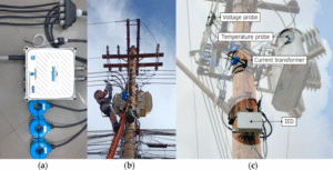
Measure or retrieve (from smart meters, SCADA, power quality meters):
- kW, kVAr, kVA
- PF
- Three-phase currents and voltages
- Maximum demand (MD) over a defined interval (e.g., 15-min)
- Phase imbalance indicators (current unbalance, neutral current at LV)
Key metric
- Loading (%) = S_actual / S_rated × 100%
Interpretation in planning terms:
- <50% sustained: investigate oversizing vs. growth plan (do not rush replacement if growth is imminent and justified).
- 75–90% typical: often a stable operating region.
- Near/over 100%: evaluate corrective actions (load transfer, capacity upgrade, PF improvement, phase balancing, harmonic mitigation).
2) Thermal and condition checks (what determines lifespan and risk)
Electrical loading is necessary but not sufficient. Confirm thermal performance10 and condition trends, especially under high ambient temperatures or restricted ventilation.
Recommended checks (as applicable):
- Oil or winding temperature indications
- Ambient temperature correlation
- Evidence of abnormal heating under harmonic-rich loads
- For LV networks: excessive neutral current and overheating risks due to imbalance
3) Practical corrective actions before replacement
If loading is high, a transformer upgrade is not the only lever. Common mitigation options include:
- PF correction11 to reduce kVA demand
- Phase balancing to reduce worst-phase stress
- Harmonic filtering or load segregation for VFD/UPS/charger-heavy feeders
- Operational switching strategy (seasonal or time-of-day transformer operation where multiple units exist)
How to calculate transformer load capacity in kVA?
This section provides repeatable formulas and examples that engineering and procurement teams can both verify.
1) Convert peak kW to kVA using power factor
- S (kVA) = P (kW) / PF
Example: single transformer
- Peak diversified load: (P_{peak} = 3500\,kW)
- Power factor: (PF = 0.8)
- Required kVA at peak:
(S_{peak} = 3500 / 0.8 = 4375\,kVA)
If you target 85% typical loading:
- (S_{rated} \ge 4375 / 0.85 \approx 5147\,kVA)
Choose the next standard rating based on utility practice and manufacturer catalog options.
2) Two-transformer selection using a shared-load planning factor
If two transformers are planned and operating strategy supports it, one practical approach is selecting each unit to cover a portion of the peak—while maintaining contingency logic and avoiding chronic light-load.
A commonly used planning factor in practice is selecting each unit around 70% of the total peak (project-specific):
- (S{each} = 0.7 \times \dfrac{P{peak}}{PF})
Example
- (S_{each} = 0.7 \times 3500 / 0.8 = 3062\,kVA)
A standard selection could be 3150 kVA per unit, with an operating plan aligned to load profile and reliability requirements.
Note: The “70%” factor must be justified by your network topology, allowable load shedding, N-1 intent, and whether the two units are expected to run in parallel or serve segmented feeders.
3) Current calculation (useful for switchgear, cable, and protection checks)
For three-phase systems:
- I (A) = S (kVA) × 1000 / (√3 × V_LL (V))
This is essential when transformer capacity changes affect LV bus rating, breaker selection, busbar temperature rise, and cable thermal limits.
4) Phase-based calculation example (LV imbalance scenario)
If phase totals are:
- (P_A = 10\,kW), (P_B = 9\,kW), (P_C = 11\,kW)
Then: - (P_{max} = 11\,kW)
- (P_{3\phi} \approx 3 \times 11 = 33\,kW)
- With (PF = 0.8):
(S = 33 / 0.8 = 41.25\,kVA) - If planning for 85% loading:
(S_{rated} \ge 41.25 / 0.85 \approx 48.5\,kVA) → choose 50 kVA (standard step)
Practical Takeaways for Grid Expansion Projects
- Base sizing on diversified peak demand, not nameplate sums.
- Convert kW → kVA using measured or defensible PF.
- Treat phase imbalance7 as a sizing and risk factor at LV.
- Keep normal loading near a rational band (often 75–90%) to balance reliability and economics.
- Explicitly check motor starting (voltage dip and thermal stress).
- Use multi-transformer schemes only when critical load + sufficient base load justify it; otherwise, light-loading becomes costly.
- For large seasonal swings, two smaller units with staged operation often improve annual efficiency and operational flexibility.
- After commissioning, validate with measured kVA, PF, phase currents, and temperature trends—then optimize with PF correction, phase balancing, or load transfers before resizing.
Conclusion
Evaluating transformer capacity during distribution grid expansion is fundamentally a systems decision. The most reliable outcomes come from combining:
- current load realities (measured or defensible diversified peaks),
- future growth assumptions (explicit and reviewable),
- reliability strategy (critical loads, contingency intent),
- and economic discipline (losses, operating strategy, replacement risk).
When these are documented and checked against real operating data, capacity selection becomes predictable—avoiding both “big horse pulling a small cart” inefficiency and overload-driven reliability risk.
-
Understanding the drawbacks of oversized transformers can prevent inefficiencies. ↩
-
Verified load data is critical for accurate transformer sizing and performance. ↩
-
Voltage regulation is vital for ensuring stable power delivery from transformers. ↩ ↩
-
Motor starting can significantly impact transformer load and sizing decisions. ↩
-
Understanding seasonal variability is crucial for optimizing transformer capacity. ↩ ↩
-
Power factor significantly impacts the calculation of transformer capacity. ↩
-
Addressing phase imbalance is crucial for optimal transformer performance. ↩ ↩ ↩
-
Understanding loading bands helps maintain efficient transformer operation. ↩
-
Diversified peak demand is a key concept for accurate transformer capacity planning. ↩
-
Thermal performance assessment is key to ensuring transformer longevity and reliability. ↩
-
PF correction can enhance transformer efficiency and reduce operational costs. ↩