Distribution grid expansion projects rarely fail because of a single “wrong transformer”—they fail because of mismatched configuration decisions: vector group incompatibility that blocks paralleling, grounding choices that create protection blind spots, or a connection that amplifies harmonics from modern loads (EV charging, PV inverters, data centers). This article summarizes the transformer configuration approaches most commonly used in distribution expansion, with a practical focus on how utilities and EPC teams keep designs scalable, parallelable, and compliant.
What are the common configurations of transformers?
In distribution projects, “configuration” typically refers to winding connections1 and vector group2 (phase displacement), plus whether a neutral is available and how it is grounded.
1) Winding connection families (Δ / Y / Z)
Three-phase transformer connections are usually described by the primary (HV/MV) and secondary (LV) winding connection:
-
Δ–Δ (Delta–Delta)
- Strengths: robust for balanced 3φ loads; can run as open-delta (V–V)3 at reduced capacity if one unit is out; delta provides a path for certain harmonic currents.
- Limits: no neutral on LV unless you add a grounding transformer; less suitable for mixed single-phase LV supply.
-
Y–Y (Wye–Wye / Star–Star)
- Strengths: neutrals available on both sides; economical winding insulation utilization; easy to provide LV neutral.
- Limits: can be sensitive to zero-sequence behavior4, triplen harmonics5, and ferroresonance if grounding and system conditions aren’t handled carefully. Often stabilized by adding a delta tertiary.
-
Δ–Y (Delta–Wye / Delta–Star)
- Strengths: arguably the most versatile for distribution: LV neutral available, good behavior under unbalanced secondary loading, and the delta side helps manage zero-sequence/harmonic interaction with upstream systems.
- Limits: introduces 30° phase displacement (vector group dependent), so paralleling must be managed.
-
Y–Δ (Wye–Delta)
- Strengths: HV wye can reduce per-phase insulation requirement (line-to-neutral), and a grounded HV neutral may be desired at certain interfaces.
- Limits: LV delta does not provide a neutral for common LV distribution without additional measures.
-
Zigzag (Z) grounding transformer (not a power transformer “main” connection, but a common configuration tool)
- Used to create a neutral or improve ground-fault performance6 in systems where delta prevents a solid neutral reference.
Practical rule: in distribution expansion, the “best” connection is the one that matches existing bus vector group, meets grounding and protection philosophy, and supports future paralleling without rework.
2) Vector group and phase displacement
Vector group indicates how LV phasors are shifted relative to HV (commonly 0° or ±30° for distribution transformers). This is critical for:
- Paralleling and load sharing
- Backfeeding / reverse power (DER integration)
- Metering and protection coordination
3) Grounding configuration (system impact)
Grounding decisions affect:
- Earth-fault current magnitude
- Protection sensitivity and selectivity
- Temporary overvoltages
- Insulation coordination
What is the most common transformer setup?
For most modern distribution expansion scenarios—especially where the LV side serves mixed 3φ + 1φ loads—Δ–Y with grounded LV neutral is the workhorse configuration.
Why Δ–Y is so widely used in expansion
- LV grounded neutral supports real distribution reality: single-phase services, unbalanced feeders, and widespread 1φ tapping.
- Better tolerance to customer-side unbalance: unbalanced LV currents do not force the upstream MV side into excessive neutral/zero-sequence issues in the same way as some other connections.
- Harmonic behavior is generally manageable: delta provides a circulating path for certain triplen harmonic components, reducing their impact on the upstream network (system design still matters—don’t treat this as “harmonics solved”).
- Protection and fault detection are straightforward on LV: grounded neutral improves earth-fault detection, especially for dense LV networks.
Typical project “default” setups (by context)
- Urban / high-density load growth (commercial + residential mix): Δ–Y (grounded neutral), sized with realistic diversity and growth margin.
- Industrial blocks with largely balanced 3φ loads: Δ–Δ or Δ–Y depending on whether LV neutral is required and on existing system standards.
- DER-heavy feeders (PV, storage, EV hubs): often still Δ–Y, but with tighter requirements for impedance, thermal margin, tap range7, and harmonic performance.
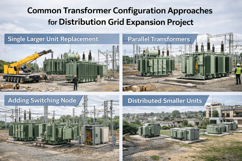
What’s Common Transformer Configuration Approaches for Distribution Grid Expansion Project ?
Grid expansion projects prioritize configurations that reduce schedule risk and preserve future flexibility. The most common approaches below are less about “one right diagram” and more about ensuring the system can be extended without redesign.
1) Start from the single-line diagram (SLD) and identify the “constraints”
Before selecting a connection, teams confirm:
- Existing bus vector group (what’s already installed and what must be paralleled)
- Grounding philosophy (solid, resistance grounded, isolated, Petersen coil, etc.)
- Protection scheme (earth-fault detection method, differential protection scope, feeder relays)
- Load composition (3φ motors vs mixed LV, unbalance severity, harmonic sources)
- DER presence and export scenarios (reverse power, voltage control needs)
Single-line diagrams (SLD / one-line drawings) simplify three-phase systems into a single representation and highlight key components:
- Buses as heavy lines (collection and distribution nodes)
- Breakers/fuses as switching/protection elements (open/closed state often shown by symbol fill)
- Motors/fans/pumps (cooling auxiliaries, station service loads) commonly shown with a motor symbol
SLD discipline matters because transformer configuration is a system decision, not a component decision.
2) Paralleling-first design (the “no surprises later” approach)
To add capacity with minimal outage time, expansion designs aim for compatibility in:
- Vector group / phase displacement
- Voltage ratio and tap range7
- % impedance (Z%) and impedance tolerance
- X/R ratio (influences fault current sharing)
- kVA rating and cooling class8
- Loss evaluation (to avoid large no-load/load loss mismatch that can cause unequal operation economics)
Field reality: A transformer that “electrically works” may still be operationally unacceptable if it can’t parallel with existing units or if it forces relay setting changes across the feeder.
3) Use open-delta (V–V) strategically in early-stage growth
In low-load or emerging areas, utilities sometimes deploy two single-phase transformers in open delta to supply 3φ service at reduced capacity:
- Benefits: lower initial capex; faster deployment; add the third unit later.
- Limits: capacity is reduced and losses/regulation can be worse than a full bank; not ideal for heavy motor starts or rapid load growth.
4) Add a tertiary winding when stabilization or auxiliary supply is needed
A delta tertiary can be used to:
- Provide a path for triplen harmonics5
- Improve stability in Y–Y applications
- Supply station service or auxiliary loads
- Support certain protection or grounding strategies
This is common in substation transformers and in some distribution nodes where system behavior requires it.
5) Future-proofing for DER (PV/storage/EV) without overcomplicating the base design
DER changes the “normal” direction of power flow and can stress:
- Voltage regulation (tap changer duty)
- Thermal loading (peaks can shift)
- Harmonics (inverter spectra)
- Ground-fault behavior (depending on inverter grounding and transformer connection)
Common mitigation steps:
- Confirm tap range and regulation method (fixed taps vs OLTC where applicable)
- Specify thermal margin and realistic load cycle
- Define harmonic limits9 and measurement methods in procurement specs
- Coordinate grounding and protection end-to-end (utility + customer interface)
What is the difference between Dyn5 and Dyn11?
Dyn5 and Dyn1110 are vector groups describing winding connection and phase displacement.
- D = HV winding is Delta
- y = LV winding is Wye (star)
- n = LV neutral is brought out
- The number (5 or 11) is the clock notation for LV phase displacement relative to HV:
- Each “hour” = 30°
- 5 → 150° displacement
- 11 → 330° displacement (equivalently -30°)
Practical meaning in distribution projects
- Dyn11 (−30°) is extremely common in many IEC-influenced distribution practices because it standardizes how LV is shifted relative to HV and aligns with established paralleling conventions.
- Dyn5 (+150°) is not “wrong”—it’s simply a different displacement that must be managed.
Why the difference matters
1) Paralleling:
Transformers can generally only be paralleled if they share the same vector group (same displacement). Dyn5 and Dyn11 cannot be paralleled without phase-shifting measures—doing so risks circulating currents and severe overheating.
2) Protection and phasing:
CT polarity, relay vector compensation, and metering schemes depend on consistent phase relationships.
3) System standardization:
Mixed vector groups across a grid complicate operations, spares strategy, and emergency replacement.
Procurement tip: always state the required vector group explicitly in project specs and verify it against the existing substation/feeder standard before ordering.
Which type of transformer is used in a distribution system?
Distribution systems use several transformer “types,” selected by location, safety, and installation method—in addition to electrical configuration.
1) By installation (where it sits)
- Pole-mounted transformers (overhead networks)
- Common in rural/suburban systems; can be single-phase or three-phase banks.
- Pad-mounted transformers (underground distribution)
- Widely used in urban/suburban underground networks; often compartmentalized for switching and protection.
- Substation distribution transformers
- Larger kVA/MVA units feeding primary distribution feeders; often include OLTC and more advanced monitoring.
2) By insulation/cooling medium
- Oil-immersed (liquid-filled)
- Most common outdoors due to strong thermal performance and cost effectiveness.
- Dry-type (cast resin or VPI)
- Common indoors or where fire/environmental constraints dominate (commercial buildings, industrial plants, transit hubs).
3) By phase arrangement
- Three-phase units or banks of three single-phase units
- Choice depends on transport limits, maintenance philosophy, spares strategy, and outage resilience.
4) Typical distribution “standard” pairings (examples)
- MV→LV service transformers: often Δ–Y (neutral grounded) where LV neutral is needed.
- Feeder/regional interface: can vary; often depends on grounding and existing utility practice, sometimes involving Y–Δ or Y–Y with tertiary delta.
The most accurate answer is: distribution systems use the transformer type that matches the network’s grounding, protection, and service needs, and the configuration that matches the existing vector group standard for safe paralleling and future expansion.
Closing: configuration decisions that reduce rework and outage risk
In distribution grid expansion, transformer configuration is less about “textbook correctness” and more about system compatibility and operational scalability. The most successful projects lock down these items early:
- Required vector group (e.g., Dyn11) to guarantee paralleling compatibility
- Grounding and neutral strategy aligned with protection philosophy
- Impedance and regulation requirements to ensure stable load sharing and voltage quality
- A forward-looking view of DER, harmonics, and evolving load composition
If you want fewer change orders and fewer commissioning surprises, treat transformer configuration as a grid integration decision—validated on the single-line diagram and checked against what is already installed.
-
Understanding winding connections is crucial for selecting the right transformer for your project. ↩
-
Learn about vector groups to ensure proper transformer operation and compatibility. ↩
-
Open-delta configurations can be a cost-effective solution for low-load areas. ↩
-
Understanding zero-sequence behavior helps in managing unbalanced loads effectively. ↩
-
Learn about triplen harmonics to mitigate their impact on transformer performance. ↩ ↩
-
Ground-fault performance is critical for safety and reliability in electrical systems. ↩
-
Understanding tap range is essential for voltage regulation in transformer applications. ↩ ↩
-
Choosing the right kVA rating and cooling class ensures optimal transformer operation. ↩
-
Harmonic limits are crucial for maintaining power quality in electrical systems. ↩
-
Understanding Dyn5 and Dyn11 is key for proper transformer paralleling and operation. ↩