As utilities and EPCs work to modernize and expand distribution grids, the technical specifications of power and distribution transformers become paramount. Faced with aging infrastructure, rising demand, and the integration of distributed energy resources (DERs), project engineers and procurement managers must make strategic decisions that balance immediate costs with long-term reliability and scalability.
Choosing the right transformer winding configuration is not merely a design detail; it is a foundational decision that impacts system stability, fault tolerance, and future-proofing. An incorrect choice can lead to operational inefficiencies, complicated parallel operations, and challenges in managing harmonic distortion.
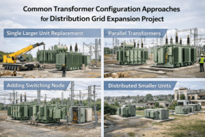
This article outlines five critical configuration strategies for distribution grid expansion projects, providing the engineering context needed to specify transformers that ensure performance, reliability, and seamless grid integration.
1. Master the Workhorse: The Delta-Wye (Δ-Y) Configuration
For most commercial, industrial, and high-density residential distribution applications, the Delta-Wye (Δ-Y) configuration1 is the undisputed standard. Its prevalence is rooted in a unique combination of advantages that directly address common grid challenges.
- Why It Matters: Grid expansion often involves serving a mix of three-phase and single-phase loads, which can lead to unbalanced conditions. Furthermore, modern loads (VFDs, electronics) introduce harmonics that can destabilize the grid. The Δ-Y configuration provides an elegant solution to both issues.
- Engineering Breakdown:
- Grounded Neutral on Secondary2: The Wye-connected secondary provides a stable, accessible neutral point. This is essential for grounding the low-voltage system, ensuring safety, and enabling the supply of single-phase loads (e.g., 277V lighting and 480V three-phase motors from a 480Y/277V system, or 230V single-phase loads from a 400Y/230V system).
- Harmonic Suppression3: The Delta-connected primary winding traps third-order (triplen) harmonics, preventing them from circulating back into the medium-voltage utility grid4. This filtering action improves power quality and protects upstream equipment.
- Load Balancing5: The Delta primary helps to balance the currents drawn from the three-phase supply, even when the secondary Wye loads are unbalanced.
For grid expansion projects, specifying a Δ-Y transformer is often the default, most reliable choice for stepping down from a medium-voltage feeder to a low-voltage service point.
2. Ensure Scalability with Correct Vector Group Paralleling
As load centers grow, transformers must often be operated in parallel to increase capacity and provide redundancy. Successful parallel operation is impossible without precisely matching key parameters, chief among them the vector group6.
- Why It Matters: Attempting to parallel transformers with mismatched vector groups will result in a significant voltage difference between the corresponding phases. This creates large circulating currents that will damage the windings and cause protective devices to trip, leading to a complete outage.
- Engineering Breakdown:
- Understanding Vector Groups (e.g., Dyn11, Dyn5): The vector group designation describes the winding connection (D for Delta primary, y for Wye secondary, n for accessible neutral) and the phase angle relationship between the high-voltage (HV) and low-voltage (LV) windings. The number represents the phase shift on a clock face, where each hour is a 30° displacement.
- Dyn11 vs. Dyn57:
- Dyn11: The LV winding voltage lags the HV winding voltage by 30° (11 o’clock). This is the most common standard in IEC markets and many other regions for distribution transformers.
- Dyn5: The LV winding voltage leads the HV winding voltage by 150° (5 o’clock).
- Project Application: When adding a new transformer to an existing substation, it is absolutely critical that the new unit has the same vector group (e.g., Dyn11) as the existing units. For new projects, standardizing on a single vector group like Dyn11 simplifies future expansion and sourcing of spare units.
3. Implement Flexible Growth with Delta-Delta (Δ-Δ) and Open-Delta (V-V)
While less common for general distribution, the Delta-Delta (Δ-Δ) configuration offers unique advantages for specific industrial applications and phased grid rollouts, particularly in regions following ANSI/IEEE practices.
- Why It Matters: In rural or developing areas, initial electrical demand may not justify the capital expense of a full three-phase transformer bank. The open-delta configuration provides a cost-effective path for staged growth.
- Engineering Breakdown:
- Open-Delta (V-V) Operation8: This approach uses two single-phase transformers connected in a "V" to supply a three-phase load. It can deliver approximately 58% of the capacity of a full three-transformer Delta-Delta bank. This allows utilities to establish three-phase service with a lower initial investment.
- Scalability: As load grows, a third transformer can be added to close the delta, forming a full Δ-Δ bank and increasing capacity to 100% without replacing the original two units.
- Fault Tolerance9: A key advantage of a Δ-Δ bank is that if one of the three transformers fails, the remaining two can continue to operate in an open-delta configuration, supplying critical loads at reduced capacity until a replacement is installed. This is a significant reliability feature for industrial processes where downtime is costly.
4. Integrate Renewables and DERs10 with Purpose-Built Configurations
The rise of solar farms, battery storage (BESS), and EV charging stations introduces bi-directional power flow and significant harmonic content from power inverters. Transformer configuration is a key tool for managing these new grid dynamics.
- Why It Matters: Inverter-based resources can inject high-frequency harmonics and DC currents, while bi-directional flow changes fault current behavior. The transformer acts as the critical interface between the DER and the utility grid, and its configuration must be selected to maintain stability and safety.
- Engineering Breakdown:
- Typical Configuration: A step-up transformer at a solar or wind farm is often configured as Wye-Grounded (LV Side) – Delta (HV Side)11.
- The Wye-grounded low-voltage side provides a necessary neutral connection for grounding the inverter output and facilitating ground-fault detection.
- The Delta-connected high-voltage side (grid side) effectively blocks zero-sequence currents and triplen harmonics from flowing back into the distribution or transmission system.
- For step-down applications feeding large EV charging depots, a standard Delta (MV) – Wye (LV) configuration remains robust, offering a stable grounded neutral for the chargers while isolating harmonics from the utility feeder.
- Typical Configuration: A step-up transformer at a solar or wind farm is often configured as Wye-Grounded (LV Side) – Delta (HV Side)11.
5. Manage System Stability with Wye-Wye (Y-Y) and Tertiary Windings
The Wye-Wye (Y-Y) configuration12 is economical due to reduced winding insulation requirements (phase-to-neutral voltage is 1/√3 of phase-to-phase voltage). However, it comes with significant stability risks if not implemented correctly.
- Why It Matters: Y-Y transformers are susceptible to severe third-harmonic voltage distortion13 and potential over-voltages from ferroresonance, especially with floating neutrals. These issues can cause equipment malfunction and insulation failure.
- Engineering Breakdown:
- The Challenge: Without a Delta winding, third harmonics generated in the core have no path to circulate and instead distort the phase voltage waveforms. An ungrounded or poorly grounded neutral can also shift dramatically during unbalanced faults.
- The Solution: Tertiary Winding: To mitigate these risks, a Y-Y power transformer is often specified with a third, Delta-connected "tertiary" winding. This winding is typically of a lower voltage rating and may be unloaded or used to power auxiliary station services. Its primary purpose is to create a circulating path for third-harmonic currents, effectively trapping them and stabilizing the phase voltages.
For high-voltage transmission-to-distribution substations, a Y-Y transformer with a Delta tertiary provides a reliable way to get grounded neutrals on both the primary and secondary sides while controlling harmonic issues.
Conclusion: Engineering Partnership for Reliable Grid Expansion
The selection of a transformer configuration is a strategic engineering decision with long-term consequences for grid reliability, operational efficiency, and future expansion capability. As illustrated, each approach—from the versatile Delta-Wye to the specialized Y-Y with tertiary—offers a distinct set of trade-offs.
Success in any grid expansion project depends on a clear understanding of these trade-offs and a manufacturing partner capable of delivering transformers that meet precise technical specifications for voltage, impedance, and vector group.
As an engineering-driven OEM/ODM manufacturer, YEEG Transformer specializes in producing transformers that comply with both IEC and IEEE standards. Contact our engineering team to discuss your project’s specific configuration requirements and ensure your grid expansion is built on a foundation of reliability and performance.
-
Explore the benefits of the Delta-Wye configuration, which addresses common grid challenges effectively. ↩
-
Learn about the significance of a grounded neutral for safety and stability in low-voltage systems. ↩
-
Discover how harmonic suppression enhances power quality and protects equipment from damage. ↩
-
Explore the role of medium-voltage utility grids in electrical distribution and their operational challenges. ↩
-
Understand the importance of load balancing for maintaining stability in three-phase supply systems. ↩
-
Find out why matching vector groups is crucial for successful transformer parallel operation. ↩
-
Explore the key differences between Dyn11 and Dyn5 to make informed decisions for your projects. ↩
-
Learn how Open-Delta operation provides a cost-effective solution for phased growth in electrical systems. ↩
-
Discover the reliability features of Delta-Delta configurations that ensure continuous operation during faults. ↩
-
Understand the challenges and solutions for integrating renewables and distributed energy resources into the grid. ↩
-
Explore how this configuration manages harmonics and stabilizes inverter outputs in renewable applications. ↩
-
Learn about the potential stability risks of Wye-Wye configurations and how to mitigate them. ↩
-
Understand the causes and effects of third-harmonic voltage distortion on equipment performance. ↩